Parallel port programming on DOS - An introduction.
From the point of view hardware, a port is an interface (a kind of door) that allows a computer to communicate with external devices. The parallel port is a type of interface found on early computers, in particular the IBM PC. The name "parallel" refers to the way the data is sent; parallel ports send multiple bits of data at once, as opposed to serial ports, that send bits one at a time. To do this, parallel ports require multiple data lines in their cables and port connectors and tend to be larger than contemporary serial ports, which only require one data line.
There are many types of parallel ports, but the term has become most closely associated with the printer port or Centronics port found on most personal computers from the 1970s through the 2000s. It was an industry de facto standard for many years, and was mostly, but not only, used to connect a printer to the PC. The IBM Personal Computer, first released in 1981 included a variant of the Centronics interface. IBM standardized the parallel cable with a female DB-25 connector (DB25F connector) on the PC side and the 36-pin Centronics connector on the printer side. Vendors soon released printers compatible with both standard Centronics and the IBM implementation.
The Centronics handshake between the PC and the printer was normally implemented using a Standard Parallel Port (SPP) under software control. In later versions of the parallel port interface, Enhanced Parallel Port (EPP) and Extended Capabilities Port (ECP), the handshake was done by the hardware; the software needed to perform only one I/O operation to the relevant port register. If you are interested in further details, please have a look at the Parallel port article in Wikipedia.
The figure below shows the IBM-PC parallel printer port female DB-25 connector external pin layout.

|
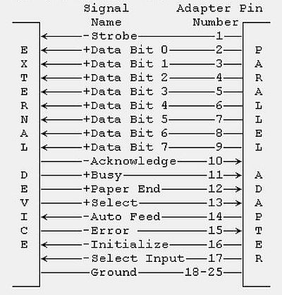
On the figure below, you can see the correspondence between the DB-25 connector pins and the signals exchanged between the computer and the printer. You can also see the direction of the different signals, either from the computer to the printer (output signals), or from the printer to the computer (input signals). To note that parallel ports could be bi-directional, some or all data signals also usable as inputs.
|
The "+" resp. "-" in front of a signal name indicates if the active signal is +5V (logical 1), or 0V (logical 0).
A PC could have up to 3 parallel ports, named LPT1: LPT2: and LPT3: respectively. Normally, there was a single one, with at the outside of the computer one DB-25 connector. For this tutorial, I use a VMware Workstation 16 virtual machine running FreeDOS. The VM has one parallel port, defined in VMware as a text file (using a physical parallel port does not work, as these are not recognized by DOS, nor by the first Windows releases, only up from Windows XP, I think).
So, externally the parallel port corresponds to a DB-25 connector (not really existing on our VM, but that's not necessary to play around with the parallel port). The question is: To what a parallel port does correspond internally? Each of the 3 possible parallel ports is internally implemented by a 3-bytes memory area (in the case of an SPP, as is supposed in the tutorial), these 3 areas starting at addresses $03BC, $0378, and $0278 respectively.
The first thing, that we have to figure out, is what's the (base) address of our parallel port. This may be done using the parallel port utilities by Parallel Technologies. You can download version 1.34 of the software from Useless Software Archive. To install just unpack the download archive to some folder (I use c:\dostools\para134).
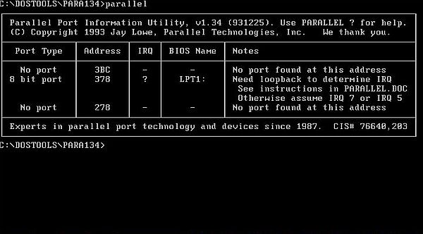
To find the available parallel ports and their addresses, run Parallel Port Information Utility (parallel.exe).
|
As you can see on the screenshot, our port LPT1: (a probably bi-directional SPP) has the base address $0378.
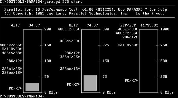
There is another program included with the para134 files: Parallel Port Performance Tester (paraspd.exe) allows to measure the speed of a given parallel port. Running it for port $0378 and with "chart" as second parameter, we get a graphical representation of our port's speed in comparison to typical values for given configurations. Seems to be rather slow...
|
The addresses of the 3 possible ports are stored in the BIOS Data Area at addresses 0040:0008 (LPT1:), 0040:000A (LPT2:), 0040:000C (LPT3:) as word (2 bytes) values; if a port does not exist, the value is 0.
A simple way to check the presence and addresses of the 3 parallel ports is to use the DOS utility debug, which allows to display the content
of a memory area. The utility is interactive, waiting for commands like -d, or -q (to quit). The following command
displays the content of 6 memory locations, starting with 0040:0008
-d 0040:0008 L6
The output on my FreeDOS machine is:
78 03 00 00 00 00
what means that LPT1: is present with address = $0378 (LPT2: and LPT3: are not present).
Of course, it is possible to write our own program to determine the available parallel ports in our FreeDOS machine. There is a problem, however: We'll have to access the BIOS Data Area, what using a programming language creating protected mode programs (such Free Pascal for go32v2) is not so evident. I did not try with the 16bit cross-compiler for DOS on Linux, that I have actually installed on Linux Mint. Instead, I chose to use Microsoft QuickBasic 4.5, that makes these kind of programs very simple, not only allowing to access memory using PEEK, but also to set the DOS real mode memory segment that has to be used thanks to DEF SEG.
Here is the code of my LPTADDR.BAS program in QuickBasic 4.5.
PRINT
PRINT "Parallel ports available on this machine."
DEF SEG = &H40
FOR i% = 1 TO 3
PRINT " LPT";
PRINT USING "#"; i%;
PRINT ":";
biosaddr% = &H8 + 2 * (i% - 1)
pdata% = PEEK(biosaddr%) + PEEK(biosaddr% + 1) * 256
IF pdata% = 0 THEN
PRINT "not found!"
ELSE
PRINT "found at address $"; HEX$(pdata%)
END IF
NEXT
PRINT
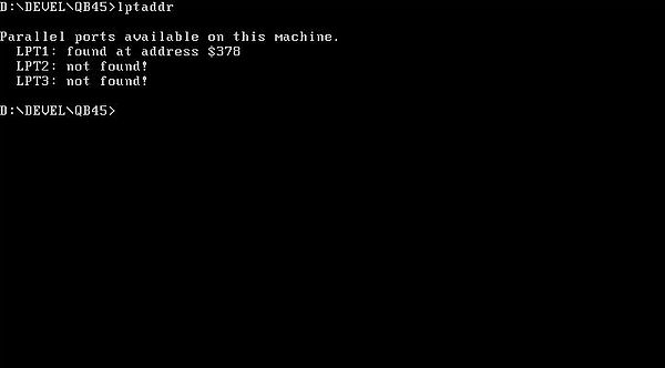
And the screenshot of the program output.
|
So, now we know that the base address of LPT1: is $378. That means that the port relative data is located at this address and the two following. The three addresses are usually named as follows: base + 0 ($378) = data register, base + 1 ($379) = status register, base + 2 ($37A) = control register.
The following figure shows these 3 registers with those bits that actually have a meaning and those who haven't ("-" meaning: bit unavailable). Note, that some of the available bits are represented with a bar above the "x". This means that these bits (actually S7, C0, C1, and C3) are inverted (compared to the logical low/high state at the corresponding pin of the DB-25 connector; cf. further down in the text).

|
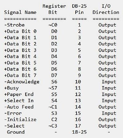
And finally, here is a table showing the correspondence between the register bits and the pins of the DB-25 connector. It also shows the corresponding signal names (these are of no real interest for us, as they essentially concern printing), and the I/O direction, where "input" means that we can apply a +5V/0V voltage to the connector pin and retrieve the low/high logical state by reading the corresponding bit in the corresponding register, and where output means that we can set/reset the bit in the concerned register and this way obtain a +5V/0V output voltage at the corresponding pin of the connector.
|
Note the inverted register bits S7, C0, C1, and C3. If, for example, we apply a +5V voltage at pin 11, register bit S7 will be set to 0. If we set C0 = 1, pin 1 will go low (voltage = 0V).
The following paragraphs of the tutorial describe simple electronic circuits connected to the LPT1: port (supposed to be at address $0378). It is supposed that you have the necessary knowledge in electronics to read and understand the circuit diagrams. And enough knowledge in Free Pascal programming to understand the sample programs.
If you have the chance to own an old computer, that includes a parallel port connector, you can build real electronic circuits and connect them as described. Caution, however: The PC parallel port can be damaged quite easily if you make mistakes in the circuits you connect to it!. All real connections, that you make, are on your own risk. In no event shall the author of this tutorial be liable for any special, direct, indirect, consequential, or incidental damage to your computer! Also, the program samples have never been tested with real circuits, thus, no guarantee that they will effectively work correctly...
In my VMware Workstation virtual machine, the LPT1: port is just a text file on the host. But, this doesn't mean that the program samples can't be used just as if there was a physical DB-25 connector with a physical electronic circuit connected to it. All we have to do is to replace the physical circuit by some software component, simulating the circuit. These software components will be implemented as subroutines to be called periodically or when the user takes a given action in the main program (if you use real circuits, these subroutines aren't necessary, of course). The task of the subroutines will mostly consist in displaying the on/off status of a LED, connected to an output pin, depending on the logical value of the corresponding register bit.(resp. setting/resetting the register bit corresponding to an input pin, when a push button connected to that pin, has been pushed/released).
Using LEDs for parallel port output.
Let's start with viewing how to proceed to connect a LED to (one of the data pins of) the parallel port. In fact, there are two ways, how we can do:
- Using an external power source: The anode of the LED has to be connected to a +5V power supply, its cathode has to be connected to one of the data pins of the parallel ports. All LEDs have to be in series with a protective resistance (something like 330 Ω or 470 Ω). The 0V pole of the power supply has to be connected to the ground of the parallel port (one of the pins 18 through 25). With this configuration, the LED will only light if the parallel port register bit, corresponding to the pin, where it is connected to, is reset (= 0).
- Driving the LEDs with the source current from the port: The anode of the LED has to be connected to to one of the data pins of the parallel ports, its cathode has to be connected to the parallel port ground (one of the pins 18 through 25). Again, all LEDs have to be in series with a protective resistance (330 to 470 Ω). No external power supply is needed in this case. On the other hand, two important points to consider: 1. the current from the parallel port may not be high enough to make the LED light at full brightness; 2. when taking current from the PC parallel port, keep the load low, only up to few milliamperes. Trying to take too much current can fry the parallel port!. With this configuration, the LED will only light if the parallel port register bit, corresponding to the pin, where it is connected to, is set (= 1).
In this tutorial, we will connect the LEDs using the first way. The figure below shows the physical circuit of a LED connected to pin 2 of the parallel port connector (picture taken from Interfacing with LED at geocities.ws).
![Parallel port interfacing: Connection of a LED [1] Parallel port interfacing: Connection of a LED [1]](../pics/led.jpg)
|
Here is a simpler diagram of a LED connected to the parallel port:
![Parallel port interfacing: Connection of a LED [2] Parallel port interfacing: Connection of a LED [2]](../pics/led2.jpg)
|
So, this physical circuit is made of a LED connected to pin 2 of the DB-25. The LED goes on if our program sets register bit D0 to 0; the LED goes off if our program sets register bit D0 to 1. The software component, simulating the circuit, can for example be a circle (representing the LED), completely filled if the LED is on, filled with a pattern if it is off. And the logic of the subroutine would consist in displaying a completely or partially filled circle, depending on the value of D0.
If we wanted to do all this fully seriously, we would create circuit simulation subroutines that are as generic as possible, allowing to create programs without having to write new simulation routines. This is outside the scope of the tutorial, which is finally not more than an introduction to parallel port programming. Thus, we'll create a specific simulation subroutine for each program. All of these subroutines have as (first) argument a command string, as follows:
- Command 'init': Initializing the circuit by drawing the input and output components (for example the circles representing the LEDs). The LEDs are supposed to be off at program start (imagine that there is a main switch that, when open, interrupts the current at the +5V pole of the power supply, and is only closed when we start the simulation).
- Command 'output': Switching the state of the devices, connected to the output pins (LEDs on or off, for example), depending on the value of the register bits corresponding to these pins.
- Command 'input': Pushing/releasing a given push button, or closing/opening a switch and accordingly setting the register bit corresponding to the (input) pin, where the push button or switch is connected to. Unfortunately, this is not possible (cf. further down in the text)!
I have packed all simulation subroutines in the unit SIMUL.PAS. Another unit, PORTUTIL.PAS contains some helpful subroutines to read from, resp. write to the parallel port.
Here is a part of the code of PORTUTIL.PAS.
unit PortUtil;
interface
type
Logical = 0..1;
TBit = 0..7;
const
LPTPort = $378;
LPTData = LPTPort;
LPTStatus = LPTPort + 1;
LPTCommand = LPTPort + 2;
function SetBit(Value: Byte; Bit: TBit): Byte;
function ResetBit(Value: Byte; Bit: TBit): Byte;
function IsBitSet(Value: Byte; Bit: TBit): Boolean;
function LPTDataRead: Byte;
procedure LPTDataWrite(Value: Byte);
procedure LPTDataSet(Bit: TBit);
procedure LPTDataReset(Bit: TBit);
function IsLPTDataSet(Bit: TBit): Boolean;
implementation
uses Go32;
{ Set given bit within byte value }
function SetBit(Value: Byte; Bit: TBit): Byte;
begin
SetBit := Value or (1 shl Bit);
end;
{ Reset given bit within byte value }
function ResetBit(Value: Byte; Bit: TBit): Byte;
begin
ResetBit := Value and not (1 shl Bit);
end;
{ Check if given bit within byte value is set }
function IsBitSet(Value: Byte; Bit: TBit): Boolean;
begin
IsBitSet := (Value and (1 shl Bit)) <> 0;
end;
{ Read value of LPT Data register }
function LPTDataRead: Byte;
begin
LPTDataRead := InPortB(LPTData);
end;
{ Write value to LPT Data register }
procedure LPTDataWrite(Value: Byte);
begin
OutPortB(LPTData, Value);
end;
{ Set given bit in LPT data register }
procedure LPTDataSet(Bit: TBit);
var
Value: Byte;
begin
Value := InPortB(LPTData);
Value := SetBit(Value, Bit);
OutPortB(LPTData, Value);
end;
{ Reset given bit in LPT data register }
procedure LPTDataReset(Bit: TBit);
var
Value: Byte;
begin
Value := InPortB(LPTData);
Value := ResetBit(Value, Bit);
OutPortB(LPTData, Value);
end;
{ Check if given bit in LPT data register is set }
function IsLPTDataSet(Bit: TBit): Boolean;
begin
IsLPTDataSet := IsBitSet(InPortB(LPTData), Bit);
end;
end.
The function LPTDataRead returns the actual value of the parallel port Data register. The procedure LPTDataWrite sets the value of the LPT Data register (the 8 bits) to a given byte value. The procedures LPTDataSet and LPTDataReset can be used to easily set resp. reset a given bit in the parallel port Data register. The function IsLPTDataSet can be used to check if a given bit in the parallel port Data register is set.
The other 3 functions are not related to the parallel port; they concern bit access within a byte value.
As I said above, I wrote a separate simulation procedure for each circuit and put them all in the unit SIMUL.PAS. This unit also contains some procedures constantly needed by the simulation subroutines, or convenient to be called from the main programs. Here is a part of the code:
unit Simul;
interface
procedure SDelay(D: Real);
implementation
uses
Crt, Graph, PortUtil;
type
TLed = record
PosX: 0..639;
PosY: 0..479;
Color: Word;
Status: Logical;
end;
{ Enter graphics mode (640x480 pixels, 16 colors) }
procedure GraphInit;
var
Gd, Gm: Integer;
begin
Gd := D4bit;
Gm := m640x480;
InitGraph(Gd, Gm, ' ');
if graphResult <> GrOk then begin
Writeln('640x480x16 resolution is not supported!');
Halt(1);
end;
SetTextStyle(defaultFont, horizDir, 2);
end;
{ Pause during given number of seconds }
procedure SDelay(D: Real);
begin
Delay(Round(1000 * D));
end;
{ Draw a given LED }
procedure DrawLed(Led: TLed);
begin
SetColor(Led.Color);
if Led.Status = 1 then
SetFillStyle(SolidFill, Led.Color)
else
SetFillStyle(LtSlashFill, Led.Color);
FillEllipse(Led.PosX, Led.PosY, 20, 20);
end;
end.
The procedure InitGraph puts the display in 640×480 pixels, 16 colors graphics mode. This routine has to be called in all simulation procedures (when invoked with command = 'init'). Doing this way, the programmer of the main program has not to bother with the display mode. The routine also sets the actual font to the default font, size = 2. This is rather large, so if you want to display a longer line of text, you'll have to set size = 1.
The procedure SDelay pauses execution during a given number of seconds. It may be called from main programs where the LED output changes after a given time (as in our blinker program sample, for example). The procedure is implemented here by calling the Delay function of the Crt unit. This seems to work rather well. A (better) alternative would be to write a routine based on the passed system time.
The LED components of the simulated circuits are defined as records, defining their display position (coordinates of the center of the circle), their color, and their state: 1 = LED on (lighting), 0 = LED off (not lighting). The procedure DrawLed can be called by the simulation procedures to display a given LED. If the LED status is 1, a solid-colored circle is drawn, if the status is 0, a pattern is used.
Note: All of the following program samples have been written using Free Pascal for go32v2 and have been tested on a FreeDOS 1.3 RC5 VMware Workstation 16 virtual machine. Port input/output is done using the InPortB() and OutPortB() routines available in the Go32 unit. Graphics are done using the routines of the Graph unit.
Program sample 1: Simple blinker.
The circuit is made of a single LED, connected to pin 2 of the parallel port connector. The program should make this LED blink, with a given on-state phase duration, and a given off-state phase duration.
The program logic of the simulation subroutine for the simple blinker circuit is elementary. When called with command = 'init', an off-state LED has to be drawn, when called with command = 'output', either an on- or an off-state LED has to be drawn, the state of the LED depending on the value of the LPT1: Data register bit 0 (bit D0). Here is the code:
{ Circuit simulation: Simple blinker }
procedure Simul_Blinker(Command: string);
var
Data: Byte;
Led: TLed;
begin
with Led do begin
PosX := 60;
PosY := 60;
Color := LightRed;
end;
if Command = 'init' then begin
GraphInit;
SetColor(White);
Rectangle(20, 20, 100,100);
Led.Status := 0;
DrawLed(Led);
end
else if Command = 'output' then begin
Data := LPTDataRead;
if IsBitSet(Data, 0) then
Led.Status := 0
else
Led.Status := 1;
DrawLed(Led);
end;
end;
Remember that our LED is connected with its anode to the +5V pole of the power supply, thus, it lights up (status = 1) if D0 = 0!
And here is the code of the program sample BLINKER.PAS that controls the blinking of the LED connected to pin 2 of the parallel port connector. The duration of the LED's on-state and off-state are supposed to be entered as command line arguments.
{ Simple blinker }
program Blinker;
uses
SysUtils, Crt, Graph, PortUtil, Simul;
var
Data: Byte;
DurationOn, DurationOff: Real;
Key: Char;
begin
if ParamCount <> 2 then begin
Writeln('Invalid number of command line arguments!');
Halt(1);
end;
DurationOn := StrToFloat(ParamStr(1));
DurationOff := StrToFloat(ParamStr(2));
Simul_Blinker('init');
SetColor(White);
OutTextXY(20, 150, 'Simple blinker.');
OutTextXY(20, 190, ' LED on-stage duration = ' + ParamStr(1) + ' s.');
OutTextXY(20, 215, ' LED off-stage duration = ' + ParamStr(2) + ' s.');
OutTextXY(20, 255, 'Hit ENTER to let the LED blink...');
OutTextXY(20, 280, 'To terminate the program hit ESC.');
Readln;
Key := #255;
repeat
if Key <> #27 then begin
LPTDataReset(0);
Simul_Blinker('output');
SDelay(DurationOn);
end;
if KeyPressed then begin
Key := ReadKey;
if Key = #0 then
Key := ReadKey;
end;
if Key <> #27 then begin
LPTDataSet(0);
Simul_Blinker('output');
SDelay(DurationOff);
end;
until Key = #27;
CloseGraph;
end.
Some general notes concerning the programs using SIMUL.PAS:
- At program start, call the simulation procedure with argument = 'init'. This puts the display into graphics mode, then draws the components of the circuit.
- Each time that, with a real circuit, the output components (such as the LEDs) change their state, call the simulation procedure with argument = 'output' to redraw the output components, depending on the register bits corresponding to the pins where the LEDs are connected to.
- Before terminating the program call the procedure CloseGraph in order to put the display into text mode again.
- Use the Crt unit functions KeyPressed and ReadKey to control the program during the time where the simulation is running (ex: test for ESC pressed to terminate the simulation and the program). Note, that the code associated with a given key read is only executed when the Delay procedure has exited. This shouldn't normally cause any problems...
The screenshots show the execution of BLINKER.EXE: on the left screenshot, the LED is on, on the right screenshot, it is off.
![LPT programming on DOD: Simple blinker [1] LPT programming on DOD: Simple blinker [1]](../screenshots/dos_lpt4a.jpg)
|
![LPT programming on DOD: Simple blinker [2] LPT programming on DOD: Simple blinker [2]](../screenshots/dos_lpt4b.jpg)
|
Program sample 2: Alternate blinker.
This circuit consists of two LEDs connected to pins 2 and 3 of the parallel port connector (LED anode connected to +5V of the power supply). The program should let the two LEDs blink alternately, i.e. when LED1 is on, LED2 is off, and vice-versa. As for the previous program, the LED-on and LED-off state duration is given as command line parameters.
The program logic of the simulation subroutine Simul_Blinker2 is very similar to before. When called with command = 'init', two off-state LEDs have to be drawn, when called with command = 'output', an on-state and an off-state LED have to be drawn, the state of the LEDs actually depending on the value of the LPT1: Data register bits D0 resp. D1. Here is the code:
{ Circuit simulation: Alternate blinker }
procedure Simul_Blinker2(Command: string);
var
Data: Byte;
Led1, LED2: TLed;
begin
with Led1 do begin
PosX := 60;
PosY := 60;
Color := LightRed;
end;
with Led2 do begin
PosX := 120;
PosY := 60;
Color := LightRed;
end;
if Command = 'init' then begin
GraphInit;
SetColor(White);
Rectangle(20, 20, 160, 100);
Led1.Status := 0; Led2.Status := 0;
DrawLed(Led1); DrawLed(Led2);
end
else if Command = 'output' then begin
Data := LPTDataRead;
if IsBitSet(Data, 0) then
Led1.Status := 0
else
Led1.Status := 1;
DrawLed(Led1);
if IsBitSet(Data, 1) then
Led2.Status := 0
else
Led2.Status := 1;
DrawLed(Led2);
end;
end;
And here is the code of the program BLINKER2.PAS.
{ Alternate blinker }
program Blinker2;
uses
SysUtils, Crt, Graph, PortUtil, Simul;
var
Data: Byte;
DurationOn1, DurationOn2: Real;
Key: Char;
begin
if ParamCount > 2 then begin
Writeln('Invalid number of command line arguments!');
Halt(1);
end;
DurationOn1 := StrToFloat(ParamStr(1));
DurationOn2 := StrToFloat(ParamStr(2));
Simul_Blinker2('init');
SetColor(White);
OutTextXY(20, 150, 'Alternate blinker.');
OutTextXY(20, 190, ' LED1 on-stage duration = ' + ParamStr(1) + ' s.');
OutTextXY(20, 215, ' LED2 on-stage duration = ' + ParamStr(2) + ' s.');
OutTextXY(20, 255, 'Hit ENTER to let the LED blink...');
OutTextXY(20, 280, 'To terminate the program hit ESC.');
Readln;
Key := #255;
repeat
if Key <> #27 then begin
LPTDataReset(0);
LPTDataSet(1);
Simul_Blinker2('output');
SDelay(DurationOn1);
end;
if KeyPressed then begin
Key := ReadKey;
if Key = #0 then
Key := ReadKey;
end;
if Key <> #27 then begin
LPTDataSet(0);
LPTDataReset(1);
Simul_Blinker2('output');
SDelay(DurationOn2);
end;
until Key = #27;
CloseGraph;
end.
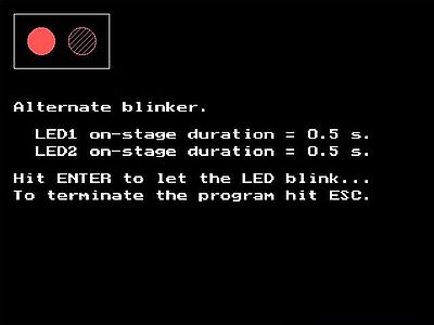
Screenshot of the program execution (with LED1 being on).
|
Program sample 3: Traffic lights.
This program sample controls two traffic lights located on two roads that cross. This means that if the cars may go on one road, they have to halt on the other, in other words, if the first traffic light is red, the second one is either red or amber (and vice-versa).
The circuit consists of 2×3 LEDs, connected to pins 2, 3, 4 (first traffic light), and pins 5, 6, 7 (second traffic light) of the parallel port connector. The LEDs connected to pins 2/5 are red LEDs, the LEDs at pins 3/6 are amber LEDs, and the LEDs at pins 4/7 are green LEDs.
The program logic of the circuit simulation routine consists in drawing the 6 LEDs (either red, amber, or green) with a LED on/off-state pattern depending on the value of the register bit corresponding to the pin where they are connected to (register bits D0 to D5 for pins 2 to 7). Here is the code.
{ Circuit simulation: Traffic lights }
procedure Simul_TrafLght(Command: string);
var
I, J, K: Integer;
Data: Byte;
Led: array[0..1, 0..2] of TLed;
begin
for I := 0 to 1 do begin
for J := 0 to 2 do begin
with Led[I, J] do begin
if I = 0 then
PosX := 60
else
PosX := 190;
PosY := (J + 1) * 60;
case J of
0: Color := LightRed;
1: Color := Yellow;
2: Color := LightGreen;
end;
end;
end;
end;
if Command = 'init' then begin
GraphInit;
SetColor(White);
Rectangle(20, 20, 100, 220);
Rectangle(150, 20, 230, 220);
for I := 0 to 1 do begin
for J := 0 to 2 do begin
Led[I, J].Status := 0;
DrawLed(Led[I, J]);
end;
end;
end
else if Command = 'output' then begin
Data := LPTDataRead;
for I := 0 to 1 do begin
for J := 0 to 2 do begin
K := I * 3 + J;
if IsBitSet(Data, K) then
Led[I, J].Status := 0
else
Led[I, J].Status := 1;
DrawLed(Led[I, J]);
end;
end;
end;
end;
The program logic of program TRAFLGHT.PAS consists in setting/resetting the register bits D0 to D5 in order to turn on/off the 6 LEDs as it would be the case for two "real world" traffic lights, starting with traffic light 1 being green (traffic light 2 being red), then becoming amber (traffic light 2 remaining red), finally becoming red (and traffic light 2 becoming green). Then, traffic light 2 becomes amber (traffic light 1 remaining red), and then red (traffic light 1 becoming green), and the whole repeating from the start. The LED on/off-phase duration is controlled by 3 command line parameters: the first traffic light's green on-phase duration, the second traffic light's green on-phase duration, the amber on-phase duration (which is the same for the 2 traffic lights). Here is the code.
{ Traffic lights }
program TrafLght;
uses
SysUtils, Crt, Graph, PortUtil, Simul;
var
Data: Byte;
DurationGreen1, DurationGreen2, DurationAmber: Real;
Key: Char;
begin
if ParamCount <> 3 then begin
Writeln('Invalid number of command line arguments!');
Halt(1);
end;
DurationGreen1 := StrToFloat(ParamStr(1));
DurationGreen2 := StrToFloat(ParamStr(2));
DurationAmber := StrToFloat(ParamStr(3));
Simul_TrafLght('init');
SetColor(White);
OutTextXY(20, 300, 'Traffic lights.');
OutTextXY(20, 340, 'Hit ENTER to start traffic lights...');
OutTextXY(20, 380, 'To terminate the program hit ESC.');
Readln;
Key := #255;
repeat
if Key <> #27 then begin
// Traffic light 1 -> green, traffic light 2 -> red
LPTDataReset(2); LPTDataSet(1); LPTDataSet(0);
LPTDataReset(3); LPTDataSet(4); LPTDataSet(5);
Simul_TrafLght('output');
SDelay(DurationGreen1);
// Traffic light 1 -> amber
LPTDataSet(2); LPTDataReset(1); LPTDataSet(0);
Simul_TrafLght('output');
SDelay(DurationAmber);
end;
if KeyPressed then begin
Key := ReadKey;
if Key = #0 then
Key := ReadKey;
end;
if Key <> #27 then begin
// Traffic light 1 -> red, traffic light 2 -> green
LPTDataReset(0); LPTDataSet(1); LPTDataSet(2);
LPTDataReset(5); LPTDataSet(4); LPTDataSet(3);
Simul_TrafLght('output');
SDelay(DurationGreen2);
// Traffic light 2 -> amber
LPTDataSet(5); LPTDataReset(4); LPTDataSet(3);
Simul_TrafLght('output');
SDelay(DurationAmber);
end;
if KeyPressed then begin
Key := ReadKey;
if Key = #0 then
Key := ReadKey;
end;
until Key = #27;
CloseGraph;
end.
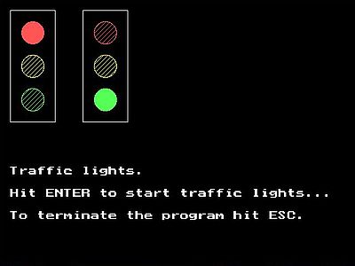
Screenshot of the program execution (with traffic light 1 being red, and traffic light 2 being green).
|
Program sample 4: Walking light.
This program sample controls 8 LEDs, switching them on (one at a time) one after the other, starting either with the first (LED "walks" from left to right), or the last (LED "walks" from right to left). The "walking" direction of the LED is specified as command line parameter.
The circuit consists of 8 LEDs connected to pins 2 - 9 of the parallel port connector.
The program logic of the simulation routine Simul_WalkLght is similar to the one of the subroutines seen before. For each of the 8 bits of the Data register, check if it is set or reset and set the status of the LED, connected to the pin corresponding to this bit, accordingly. Here is the code:
{ Circuit simulation: 8-LED walking light }
procedure Simul_WalkLght(Command: string);
var
I: Integer;
Data: Byte;
Led: array[0..7] of TLed;
begin
for I := 0 to 7 do begin
with Led[I] do begin
PosX := (I + 1) * 60;
PosY := 60;
Color := LightRed;
end;
end;
if Command = 'init' then begin
GraphInit;
SetColor(White);
Rectangle(20, 20, 520, 100);
for I := 0 to 7 do begin
Led[I].Status := 0;
DrawLed(Led[I]);
end;
end
else if Command = 'output' then begin
Data := LPTDataRead;
for I := 0 to 7 do begin
if IsBitSet(Data, I) then
Led[I].Status := 0
else
Led[I].Status := 1;
DrawLed(Led[I]);
end;
end;
end;
The logic of the program sample WALKLGHT.PAS consists in resetting successive bits in the Data register, either starting from the LSB, or the MSB (all other bits having to be set). Here is my code of this sample.
{ 8-LED walking light }
program WalkLght;
uses
SysUtils, Crt, Graph, PortUtil, Simul;
var
Data: Byte;
Direction: string;
Key: Char;
begin
if ParamCount = 0 then
Direction := 'right'
else if ParamCount = 1 then begin
Direction := ParamStr(1);
if (Direction <> 'left') and (Direction <> 'right') then begin
Writeln('Invalid command line argument!');
Halt(1);
end;
end
else begin
Writeln('Invalid number of command line arguments!');
Halt(1);
end;
if Direction = 'right' then
Data := 1
else
Data := 128;
Simul_WalkLght('init');
SetColor(White);
OutTextXY(20, 150, '8-LED walking light.');
OutTextXY(20, 190, 'Hit ENTER to make the LED walk...');
OutTextXY(20, 220, 'To terminate the program hit ESC.');
Readln;
Key := #255;
repeat
if Key <> #27 then begin
// Write value for actual LED to Data register
LPTDataWrite(255 - Data);
Simul_WalkLght('output');
SDelay(0.33);
end;
if KeyPressed then begin
// Terminate the program if ESC has been pressed
Key := ReadKey;
if Key = #0 then
Key := ReadKey;
end;
if Key <> #27 then begin
// Calculate next value
if Direction = 'right' then begin
if Data = 128 then
Data := 1
else
Data := Data * 2;
end
else begin
if Data = 1 then
Data := 128
else
Data := Data div 2;
end;
end;
until Key = #27;
CloseGraph;
end.
The code of this program uses another approach as in the samples before: Instead of setting/resetting individual bits, it calls the procedure LPTDataWrite to write all 8 bits at once to the Data register. This is easily possible here, because the successive values of a byte with just one bit set are multiples of 2. Thus, we can simply take a byte value starting with either 1 (20), or 128 (27) and then (depending on the "walking" direction of the LED) multiply or divide this value by 2 in order to get the next one. There are, however, 2 problems to solve:
- The left-most LED is connected to D0, the right-most to D7. This means that setting the left-most LED corresponds to acting on the LSB of the Data register, and setting the right-most LED corresponds to acting on the MSB of the Data register; the concerned bits varying so to say in the opposite direction of the LED "walking" direction. Thus, when "walking to the right", the original value is 1, and we have to left-shift (= multiply by 2) the value in order to act on the following LEDs. Similarly, when "walking to the left", the original value is 128, and we have to right-shift (= divide by 2) the value in order to act on the following LEDs.
- As the LEDs are powered by an external voltage supply (connected with the cathode to the parallel port), they are switched on when the corresponding bit in the Data register is reset. This means, for example, to switch on the third LED from the left, the value to write to the Data register is 11111011. This actually is the complement of the calculated value for this LED (22 = 4 = 00000100). Calculating the complement of a given byte value is simple: Just subtract the value from 255.
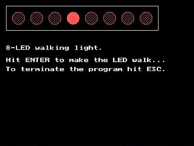
Screenshot of the program execution.
|
If you like playing with LEDs connected to the parallel port, you can use the circuit of the previous program sample to create all kind of blinking pattern. Examples: Turn LEDs on, one after the other, without turning off the LEDs already on. You can do this, starting with the left-most or the right-most LED. Or, turning on both the left-most and right-most LEDs, and then the next two in both directions... The possibilities are only limited by your own fantasy!
Using push buttons for parallel port input.
The pins 10, 11, 12, 13, and 15 of the DB-25 connector are used as data input. They correspond to the bits 6, 7, 5, 4, and 3 of the Status register (bits S6, inverted S7, S5, S4, and S3). Applying a +5V voltage to these pins, or, on the contrary connecting them to the ground, sets or resets the concerned Status register bit. For pins 10, 12, 13, and 15 applying +5 volts sets the bit; for pin 11, applying +5V resets the bit. Connecting the pins 10, 12, 13, and 15 to the ground resets the bit; connecting pin 11 to the ground sets the bit.
We can modify the signal at these input pins (and by this, modify the value of the corresponding bit in the Status register) using a push button. As for the LEDs, there are two ways to connect the push button.
![Parallel port interfacing: Connection of a push button [1] Parallel port interfacing: Connection of a push button [1]](../pics/pb1.jpg)
|
![Parallel port interfacing: Connection of a push button [2] Parallel port interfacing: Connection of a push button [2]](../pics/pb2.jpg)
|
With the first circuit (screenshot on the left), the pin is connected by default to the ground; pushing the push button connects it to +5V and the corresponding bit in the Status register is set (reset, in the case of pin 11). In the second case (screenshot on the right), the pin is connected by default to +5V; pushing the push button connects it to the ground and the corresponding bit in the Status register is reset (set, in the case of pin 11). When connecting your push button, do not forget the resistance (that should have a value of ca 6.8 kΩ to 10 kΩ).
Note: With a push button the signal at the parallel port input pin only changes during the time the button is pushed; when we release the button, the signal goes back to its default. If we need (or prefer) a circuit, where the signal doesn't go back to its default value, the simplest way is to replace the push button by a switch (that remains opened or closed).
So, with a physical circuit, data input to the parallel port is done by the user pushing (or releasing) a push button, what results in the value of the Status register bit, corresponding to the pin, where the push button is connected to, being changed. The program will have to poll this bit, and doing whatever is previewed if its value is 0 or 1. In our virtual environment, we don't have push buttons. The (probably) simplest way to simulate pushing/releasing the push button is to use the keyboard, either using one given key that toggles the push button state, or use two given keys, one to simulate pushing, the other to simulate releasing the button. Another possibility (supposing that the button is pushed and then immediately released) is to use one key that simulates pushing, and then after a small delay simulates releasing the button. Each time when the key (or one of the two keys) that simulate pushing/releasing the button has been pressed, the simulation routine has to set or reset the corresponding bit in the Status register.
As you may have guessed, this is not possible: You cannot change the Status register bits by program code! Their value always reflects the voltage at the corresponding pins of the DB-25 connector.
Whereas reading data input to the parallel port via a push button or switch is rather simple when using real hardware, the simulation of data input would require more serious coding efforts, making it fall outside the scope of this introductory tutorial. Thus, no parallel port input program samples here (sorry!). Maybe, one day, I'll write another tutorial about parallel port programming on DOS...
Connecting more complex output hardware.
LED circuits are the simplest way to play around with the parallel port. But, it is not really difficult to command more complex circuits. Some examples in the following paragraphs.
Program sample 5: Direct control of a seven-segment display.
A 7-segment display is made of seven LEDs arranged in a way that the circuit may be used to display the numbers from 0 to 9 (with a little bit of imagination, you can also use it to display a letter). There are two different kinds of 7-segment displays available. In the common-anode 7-segment display, the anodes of the 7 LEDs are internally connected; in the common-cathode 7-segment display, the cathodes of the 7 LEDs are internally connected. It's the first kind of display that we will use for our sample circuit.
In the previous examples, we have seen how to control a LED that is connected with its anode to the +5V pole of an external power source, its cathode being connected to one of the pins 2 to 9 of the DB-25 connector. That's exactly what we're doing with our 7-segment display. The figure on the left shows our circuit with the internal connections of the LEDs. The screenshot on the right shows the circuit with the external appearance of the display.
![Parallel port interfacing: Direct control of a 7-segment display [1] Parallel port interfacing: Direct control of a 7-segment display [1]](../pics/seg7a.jpg)
|
![Parallel port interfacing: Direct control of a 7-segment display [2] Parallel port interfacing: Direct control of a 7-segment display [2]](../pics/seg7b.jpg)
|
The circuit consists of the 7 LEDs of the display connected to pins 2 - 8 of the parallel port connector. A given LED is switched on, if the corresponding bit in the Data register (D0 - D6) is reset.
The 7-segment display is drawn by the procedure Draw7Segment, that has 3 arguments: the x- and y-position of the top-left corner of the surrounding box, and an array of 7 elements of type Logical (type declared as 0..1 in the PORTUTIL.PAS unit), indicating if the corresponding LED has to be switched on or off. If the LED is off, an unfilled rectangle is drawn. If it is on, a filled rectangle (a Bar with red solid-fill) is drawn. Here is the code:
{ Draw 7-segment display }
procedure Draw7Segment(X, Y: Integer; Status: array of Logical);
const
LedPos: array[0..6, 0..3] of Integer = (
(20, 40, 30, 140),
(20, 170, 30, 270),
(20, 280, 120, 290),
(110, 170, 120, 270),
(110, 40, 120, 140),
(20, 20, 120, 30),
(20, 150, 120, 160)
);
var
I: Integer;
begin
SetColor(White);
Rectangle(X, Y, X + 140, Y + 310);
for I := 0 to 6 do begin
SetColor(Black);
SetFillStyle(SolidFill, Black);
Bar(X + LedPos[I, 0], Y + LedPos[I, 1], X + LedPos[I, 2], Y + LedPos[I, 3]);
SetColor(LightRed);
SetFillStyle(SolidFill, LightRed);
if Status[I] = 1 then
Bar(X + LedPos[I, 0], Y + LedPos[I, 1], X + LedPos[I, 2], Y + LedPos[I, 3])
else
Rectangle(X + LedPos[I, 0], Y + LedPos[I, 1], X + LedPos[I, 2], Y + LedPos[I, 3]);
end;
end;
The program logic of the simulation routine is simple, not lots more that calling the procedure Draw7Segment, with as arguments the position of the display on the screen and a 6-element array of 0-or-1 values, these values being nothing else than all zeros (if the procedure is called with command "init"), resp. the complement of the corresponding bit of the Data register (if it is called with the command "output"). Here is the code.
{ Circuit simulation: 7-segment display }
procedure Simul_Segmnt7A(Command: string);
const
Status0: array[0..6] of Logical = (
0, 0, 0, 0, 0, 0, 0
);
var
I: Integer;
Data: Byte;
Status: array[0..6] of Logical;
begin
if Command = 'init' then begin
GraphInit;
Draw7Segment(40, 40, Status0);
end
else if Command = 'output' then begin
Data := LPTDataRead;
for I := 0 to 6 do begin
if IsBitSet(Data, I) then
Status[I] := 0
else
Status[I] := 1;
end;
Draw7Segment(40, 40, Status);
end;
end;
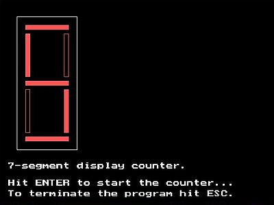
The program SEGMNT7A.PAS counts from 0 to 9 resp. from 9 to 0 (depending on the command line parameter), the numbers being displayed for a certain time on the 7-segment display. The segments that have to be turned on for a given number are stored in a two-dimensional array, more precisely an array of 10 arrays (one for each number from 0 to 9), each of these 10 arrays containing 7 0-or-1 values, telling if the corresponding segment LED has to be on (array element = 1) or off (array element = 0). To display a given number on the 7-segment display (our simulation graphic, implemented by the subroutine above, or real hardware) is to set the bits D0 to D6 of the Data register to these values complement (remember that the LEDs go on, if the register bit is reset). Here is the code:
program Segmnt7A;
uses
SysUtils, Crt, Graph, PortUtil, Simul;
const
Numbers: array[0..9, 0..6] of Logical = (
( 1, 1, 1, 1, 1, 1, 0 ),
( 0, 0, 0, 1, 1, 0, 0 ),
( 0, 1, 1, 0, 1, 1, 1 ),
( 0, 0, 1, 1, 1, 1, 1 ),
( 1, 0, 0, 1, 1, 0, 1 ),
( 1, 0, 1, 1, 0, 1, 1 ),
( 1, 1, 1, 1, 0, 1, 1 ),
( 0, 0, 0, 1, 1, 1, 0 ),
( 1, 1, 1, 1, 1, 1, 1 ),
( 1, 0, 1, 1, 1, 1, 1 )
);
var
N, I: Integer;
Data: Byte;
Direction: string;
Key: Char;
begin
if ParamCount = 0 then
Direction := 'forward'
else if ParamCount = 1 then begin
Direction := ParamStr(1);
if (Direction <> 'forward') and (Direction <> 'backward') then begin
Writeln('Invalid command line argument!');
Halt(1);
end;
end
else begin
Writeln('Invalid number of command line arguments!');
Halt(1);
end;
if Direction = 'forward' then
N := 0
else
N := 9;
Simul_Segmnt7A('init');
SetColor(White);
OutTextXY(20, 380, '7-segment display counter.');
OutTextXY(20, 420, 'Hit ENTER to start the counter...');
OutTextXY(20, 445, 'To terminate the program hit ESC.');
Readln;
Key := #255;
repeat
if Key <> #27 then begin
// Write value for actual number to Data register
for I := 0 to 6 do begin
if Numbers[N, I] = 1 then
LPTDataReset(I)
else
LPTDataSet(I);
end;
Simul_Segmnt7A('output');
SDelay(1.0);
end;
if KeyPressed then begin
// Terminate the program if ESC has been pressed
Key := ReadKey;
if Key = #0 then
Key := ReadKey;
end;
if Key <> #27 then begin
// Next number
if Direction = 'forward' then begin
Inc(N);
if N > 9 then begin
N := 0;
SDelay(1.0);
end;
end
else begin
Dec(N);
if N < 0 then begin
N := 9;
SDelay(1.0);
end;
end;
end;
until Key = #27;
CloseGraph;
end.
Screenshot of the program output.
|
Program sample 6: Indirect control of a seven-segment display.
Instead of controlling the 7-segment display directly by 7 output lines from the parallel port, we can use a BCD to 7-segment decoder/driver. This is an integrated circuit (IC) that takes a binary coded decimal as input and transforms it into a corresponding pattern for operating a seven-segment display, effectively exhibiting the numerical range from 0 to 9. There are different display decoders and drivers available for the different types of displays. Concerning LED displays, IC 74LS47 is generally used for common-anode displays, IC 74LS48 for common-cathode displays.
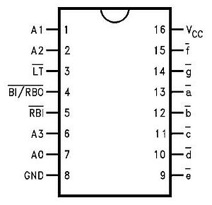
Binary coded decimal (BCD) is a coding system where every individual digit within a number corresponds to a distinct four-bit binary sequence. Examples: 5 -> 1001, 25 -> 00101001. As there are four bits needed to encode numbers from 0 to 9, the IC has 4 data input lines; as the IC controls the 7 LEDs of the 7-segment display, there are 7 data output lines. The input lines are labeled A0 to A3 (sometimes A, B, C, D are used instead). The output lines are labeled a to g, corresponding to the 7-segment display inputs with same designation. The figure below shows the pin outs of the 74LS47.
|
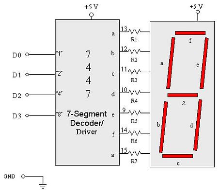
Note that the outputs a to g are active low, what well corresponds to the way that the segment LEDs of the display are connected. Thus these lines may be directly connected (via a resistance) to the corresponding input line of the 7-segment display. The input lines will be connected to pins 2 - 5 of the DB-25 connector. This corresponds to the bits D0 - D3. All that we'll have to do to display a given number from 0 to 9 is to write this number into the 4 least significant bits of the Data register.
Note: The IC also has 3 input control lines. As we don't need them here, and as they are all active low, we should connect them to +5V. For details concerning the 74LS47, please have a look at the article A Comprehensive Guide to BCD-to-7-Segment Decoder Driver at Jotrin.
The figure below shows the (somewhat simplified) circuit of an indirectly controlled 7-segment display.
|
Note: With 4 bits we can code values from 0 to 15, thus the input of the 74LS47 may fall outside the range of 0 - 9. Such input is invalid, of course, and the display will have nothing to do with a number. The figure below shows the display that we get for valid input from 0 - 9, and invalid input from 10 - 15 (note that 15 will turn all LEDs off).

|
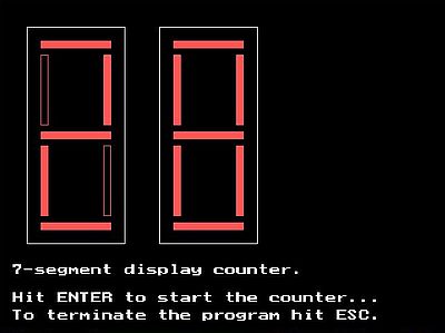
As BCD encoding of a number from 0 to 9 needs 4 bits, it is possible to put two such numbers into a byte; in other words, with one byte it is possible to BCD encode numbers from 0 to 99 (such coded numbers are called "packed decimals"). This gives us the possibility to connect two "74LS47 IC with 7-segment display" circuits to the parallel port, the first one (displaying the first digit of our two-digits number) connected to D4 - D7, the second one (displaying the second digit of our two-digits number) connected to D0 - D3. Doing this way, we can display numbers from 0 to 99.
If we had an old computer with a parallel port connector, we could connect the 2 circuits as described, and all that a counter program would have to do, is to write the number to display in BCD format to the Data register. In our virtual environment, after having written the number to the Data register, we'll have to call the simulation routine, that has to:
- Read the content of the Data register (containing the number as BCD)
- Pass the 4 MSB of the value read to a IC 74LS47 simulation routine, that outputs an array with the segment LEDs status corresponding to the IC input.
- Pass this array to the 7-segment display drawing routine (displaying the first digit of the number on the first display).
- Pass the 4 LSB of the value read to a IC 74LS47 simulation routine, that outputs an array with the segment LEDs status corresponding to the IC input.
- Pass this array to the 7-segment display drawing routine (displaying the second digit of the number on the second display).
First, let's add some useful stuff to the PORTUTIL.PAS unit:
unit PortUtil;
interface
...
function Power2(N: Integer): Integer;
function DecToBcd(N: Byte): Byte;
...
implementation
uses Go32;
{ Nth power of 2 }
function Power2(N: Integer): Integer;
// N supposed >= 0
var
M, I: Integer;
begin
M := 1;
if I > 0 then begin
for I := 1 to N do
M := M * 2;
end;
Power2 := M;
end;
{ Transform decimal byte value to BCD }
function DecToBcd(N: Byte): Byte;
// N is supposed to be between 0 and 99
begin
DecToBcd := (N div 10) * 16 + N mod 10;
end;
...
Here is the code of the IC 74LS47 simulation routine (to be added to the SIMUL.PAS unit).
{ 74LS47 BCD to 7-segment decoder simulation }
procedure Ic74ls47(var ICInput: array of Logical; var ICOutput: array of Logical);
const
// Note that these values correspond to the LED segment states,
// thus are the complements of the real world IC outputs
Outputs: array[0..15, 0..6] of Logical = (
( 1, 1, 1, 1, 1, 1, 0 ),
( 0, 0, 0, 1, 1, 0, 0 ),
( 0, 1, 1, 0, 1, 1, 1 ),
( 0, 0, 1, 1, 1, 1, 1 ),
( 1, 0, 0, 1, 1, 0, 1 ),
( 1, 0, 1, 1, 0, 1, 1 ),
( 1, 1, 1, 1, 0, 1, 1 ),
( 0, 0, 0, 1, 1, 1, 0 ),
( 1, 1, 1, 1, 1, 1, 1 ),
( 1, 0, 1, 1, 1, 1, 1 ),
( 0, 1, 1, 0, 0, 0, 1 ),
( 0, 0, 1, 1, 0, 0, 1 ),
( 1, 0, 0, 0, 0, 1, 1 ),
( 1, 0, 1, 0, 0, 1, 1 ),
( 1, 1, 1, 0, 0, 0, 1 ),
( 0, 0, 0, 0, 0, 0, 0 )
);
var
N, I: Integer;
begin
N := 0;
for I := 0 to 3 do
N := N + ICInput[I] * Power2(I);
for I := 0 to 6 do
ICOutput[I] := Outputs[N, I];
end;
And the code of the routine that simulates our two 7-segment displays with IC 74LS47 circuit.
{ Circuit simulation: Two 7-segment displays with IC 74LS47 }
procedure Simul_Segmnt7B(Command: string);
// The circuit consists of two "common anode 7-segemnt display plus IC 74LS47" circuits,
// connected to pins 2 - 5, resp. 6 - 9 of the parallel port connector.
const
AllOff: array[0..3] of Logical = (
1, 1, 1, 1
);
var
I: Integer;
Data: Byte;
ICInput: array[0..3] of Logical;
SegStatus: array[0..6] of Logical;
begin
if Command = 'init' then begin
GraphInit;
ICInput := AllOff;
Ic74ls47(ICInput, SegStatus);
Draw7Segment(40, 40, SegStatus);
Draw7Segment(230, 40, SegStatus);
end
else if Command = 'output' then begin
Data := LPTDataRead;
for I := 4 to 7 do begin
if IsBitSet(Data, I) then
ICInput[I - 4] := 1
else
ICInput[I - 4] := 0;
end;
Ic74ls47(ICInput, SegStatus);
Draw7Segment(40, 40, SegStatus);
for I := 0 to 3 do begin
if IsBitSet(Data, I) then
ICInput[I] := 1
else
ICInput[I] := 0;
end;
Ic74ls47(ICInput, SegStatus);
Draw7Segment(230, 40, SegStatus);
end;
end;
And finally the code of the program SEGMNT7B.PAS, a 2-digits counter, counting from a starting to an ending value (these two values having been entered as command line arguments).
program Segmnt7B;
uses
SysUtils, Crt, Graph, PortUtil, Simul;
var
N, NS, NE, I: Integer;
Key: Char;
Done: Boolean;
begin
if ParamCount = 0 then begin
NS := 1; NE := 99;
end
else if ParamCount = 2 then begin
NS := StrToInt(ParamStr(1)); NE := StrToInt(ParamStr(2));
if (NS < 0) or (NS > 99) or (NE < 0) or (NE > 99) then begin
Writeln('Invalid command line arguments!');
Halt(1);
end;
end
else begin
Writeln('Invalid number of command line arguments!');
Halt(1);
end;
N := NS;
Simul_Segmnt7B('init');
SetColor(White);
OutTextXY(20, 380, '7-segment display counter.');
OutTextXY(20, 420, 'Hit ENTER to start the counter...');
OutTextXY(20, 445, 'To terminate the program hit ESC.');
Readln;
Key := #255; Done := False;
repeat
if (not Done) and (Key <> #27) then begin
// Write this number as packed decimal to Data register
LPTDataWrite(DecToBcd(N));
Simul_Segmnt7B('output');
SDelay(1.0);
end;
if KeyPressed then begin
// Terminate the program if ESC has been pressed
Key := ReadKey;
if Key = #0 then
Key := ReadKey;
end;
if (not Done) and (Key <> #27) then begin
// Next number
if NS < NE then begin
Inc(N);
if N > NE then
Done := True;
end
else begin
Dec(N);
if N < NE then
Done := True;
end;
end;
until Key = #27;
CloseGraph;
end.
Screenshot of the program output.
|
Using transistors as switches.
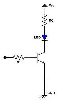
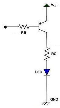
In our first examples, we have connected our LEDs directly to the parallel port. This is ok, as the load of a LED is low, for circuits with higher loads, a more important current is needed. A simple way to connect so to say any circuit to the parallel port is to use transistors. The parallel port output is connected to the base of the transistor, and the component to be switched on or off is connected to the collector. The figures below show how bipolar junction transistors may be used as a switch. On the screenshot on the left left, a NPN transistor switches the LED on if the port output pin is at logical high (the corresponding bit in the Data register equals 1). On the screenshot on the right, a PNP transistor switches the LED on if the port output pin is at logical low (the corresponding bit in the Data register equals 0).
|
|
In the case of the NPN transistor, as long as the parallel port output pin is at 0V, there is no base current and the transistor is off, i.e. there is no current flowing from the collector to the emitter; the LED is off. If now we set the Data register bit corresponding to the output pin, where the transistor is connected to, to 1, the base current begins to flow. This switches the transistor on, i.e. current can flow from the collector to the emitter; the LED goes on.
In the case of the PNP transistor, as long as the parallel port output pin is at +5V, there is no base current and the transistor is off, i.e. there is no current flowing from the emitter to the collector; the LED is off. If now we reset the Data register bit corresponding to the output pin, where the transistor is connected to, the base base current begins to flow. This switches the transistor on, i.e. current can flow from the emitter to the collector; the LED goes on.
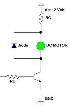
As we can use an external voltage supply delivering more than +5V (ex: +9V, +12V), and as the transistor acts an amplifier, it's possible this way not only to connect low load devices such LEDs, but also devices with higher loads, such for example a digital motor. Note, that in the case of inductive loads, it is mandatory to use a clamp diode, as shown on the picture below. The diode protects the transistor by acting as a short circuit to the high voltage generated by the inductor. You can use any general purpose diode handling a minimum of 1 A of current (ex: 1N4001, 1N4002).
|
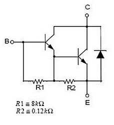
Even though the transistor amplifies the current, the load of the device connected may be too high for the collector-emitter current obtained by a single transistor. With the circuit above (supposing the transistor being a common NPN transistor), it would in fact only be possible to turn on a very small DC motor, such devices normally needing lots more current than we get with a transistor like 2N3904.
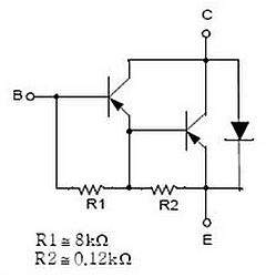
The solution consists in using a two-levels amplifier, i.e. a circuit with two transistors, the current output of the first one being used as base current for the second one. The figure below shows such circuits. On the left, with two NPN transistors (to be used for logical high switching), at the right with two PNP transistors (to be used for logical low switching).
|
|
Note: The circuit with two NPN transistors can be replaced by a circuit using a TIP 120 Darlington transistor. The circuit with two PNP transistors can be replaced by a circuit using a TIP 125 Darlington transistor.
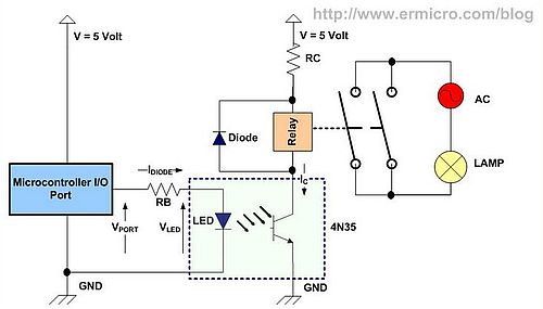
Transistor switches were commonly used to drive an electromagnetic relay connected to the parallel port. Thanks to the relay, we are able to switch "whatever we want", including devices using AC current (AC lamp, fan, heater, etc). Working with AC current will of course increase the danger to damage the parallel port (maybe even the computer). The solution consists in isolating the parallel port from the circuit connected, using an optocoupler. With an optocoupler circuit, we don’t use the transistor base terminal for driving the collector current. Instead we use the internal infrared LED to transfer the infrared LED light intensity to a phototransitor; based on this infrared LED light intensity, the phototransistor will be turned on or off. Giving more current to drive the infrared LED will effect more current to flow on the phototransistor collector.
The picture below shows the circuit to securely switch on and off an AC lamp. The parallel port output pin is connected to the infrared LED of the optocoupler; the LED’s light intensity is transferred to the phototransistor. If the phototransistor is switched on, the current can flow from its collector to its emitter. This will make the relay active, the AC circuit switch is closed, and the lamp goes on.
|
You can find lots of details and further circuit examples in the really excellent article Using Transistor as a Switch at www.ermicro.com (from where I also "borrowed" the pictures of this part of the tutorial).
LCD module interfacing.
Alphanumeric dot matrix liquid crystal display (LCD) controllers are a powerful display option for stand alone systems. Because of low power dissipation, high readability, and flexibility for programmers, LCD modules are used in many electronics devices like coin phone, billing machines or weighing machines.
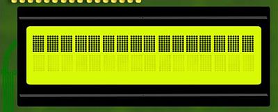
This final part of my parallel port tutorial describes how to connect a 2 rows of 16 characters, Hitachi HD44780 compatible LCD module to the parallel port.
The picture below shows the LCD module display when the power is switched on.
|
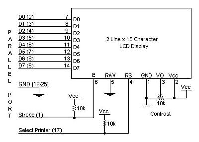
The picture below shows a typical way to connect a HD44780 LCD to the parallel port.
|
The pin layout of the HD44780 is described in the Wikipedia article Hitachi HD44780 LCD controller. Pins 7 to 14 (data bits D0 - D7) are connected to pins 2 to 9 (data bits D0 - D7) of the parallel port. In fact they are bi-directional, depending on the logical state of the R/W (read/write) pin 5. As all we want here is to write to the LCD, we can connect this pin to the ground (what sets the "write" option). The data bits of the HD44780 are used to write either data (what to display), or commands (this is simple programming code; cf. the Wikipedia article for the commands available), depending on the logical state of the RS (register select) pin 4 (0 = command, 1 = data). To be able to set/reset the RS bit, we connect pin 4 to the "Strobe" pin 1 (bit C0) of the parallel port. To program the HD44780, we must also be able to set/reset the E (clock enable) pin 6, that we connect to the "Select printer" pin 17 (bit C3) of the parallel port.
The Vee (also called V0) pin 3 is an analog input, typically connected to a potentiometer. This allows the user to control this voltage independently of all other adjustments, in order to optimize visibility by contrast adjustment.
Programming the HD44780 is relatively simple, but somewhat outside the scope of this introductory tutorial. Several Internet sites have articles about controlling an LCD display connected to the parallel port. The article Interfacing the LCD module to Parallel Port at the Electrosofts website is one of them. It includes the code of a set of C functions that do simple tasks as initializing the LCD, setting the entry mode, clearing the display, moving the cursor, writing text... Using these functions in your main program should make the programming of the HD44780 (the control of the LCD display) rather easy. Maybe, I will write some day a tutorial with Free Pascal control functions and a Free Pascal simulation routine for our virtual environment...
Click the following link to download the source code of the simulation units and program samples of the tutorial.
This ends my tutorial about the introduction to parallel port programming on DOS. I hope that you enjoyed it. If you intend to use real circuits connected to a physical parallel port, be aware that making mistakes when building your circuits may destroy the parallel port. And remember that my circuits have never be tested in a real hardware environment. Thus, no guarantee that they really work. And using them is at your own risk; in other words, should my circuits fry your parallel port (not probable, but not 100% to exclude), in no event shall the author of this tutorial be liable for any special, direct, indirect, consequential, or incidental damage to your computer!.
If you find this text helpful, please, support me and this website by signing my guestbook.