Windows 95 software: Electronic Workbench Pro - A really amazing electronics application.
If you like electronics and if you are searching for a PC application to create circuits and run them as simulations, than Electronic Workbench Professional Edition from Interactive Image Technologies Ltd. has big chances to be what you are looking for. This piece of software really amazed me by its user friendliness. Creating a circuit is intuitive and, as a difference with lots of similar software, not only the wiring mostly connects automatically with right angles, but also is it extremely simple to move components to another location, or add components somewhere in between already existing ones. And, of course, the application includes a great number of electronic devices, as well as ready-to-run circuit examples.
Electronic Workbench Professional Edition 5.12 is available for download on the VetusWare website. The download archive contains an installer program, that you can transfer onto your Windows 95 machine by burning it onto a CDROM (aka create an ISO image). I actually used an USB flush drive; in fact my Windows 95C (French language) is installed as dual boot with Windows 98SE, that supports USB2, and my two OS can exchange files on a common data partition.
Note: On the VetusWare website, they write that Electronic Workbench runs on Windows 3.1 with the Win32s extender installed. I did not try this out...
Setup is wizard-based and the only information that the user is asked for is the installation path, by default C:\EWB512. As always when a program wants to install in a folder immediately under the drive root, I changed the install directory to C:\Programs\EWB512.
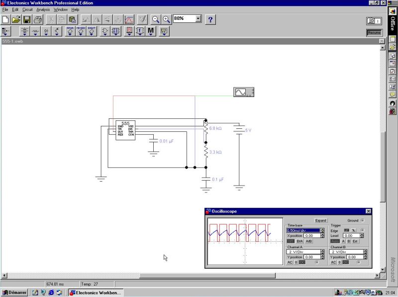
The screenshot below shows one of the included circuits, an astable multivibrator based on the 555 timer IC. Measurement instruments not only include volt- and ampere-meter, but also an oscilloscope, that allows to follow the changes of AC current and voltage versus time.

|
Use the I/O button to power on/off, i.e. to start resp. to stop the simulation. The simulation can be paused by using the corresponding button or the F9 key.
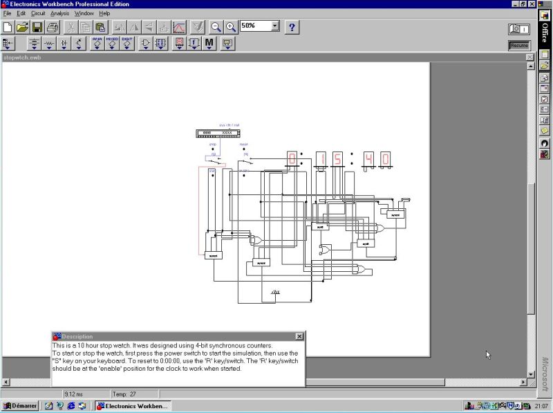
Here is the screenshot of a 10 hours electronic stop watch as another example of the included circuits.

|
To create your own circuits, click a component group on the second icon-bar. This opens a small window, showing all the components available for this group. To add a component to the circuit, just drag it to the location where you want to have it. To connect two components with a wire, click the connection end of one of the components and move the mouse to the connection end of the other. The wires are normally drawn as nice horizontal and vertical lines with right angles.
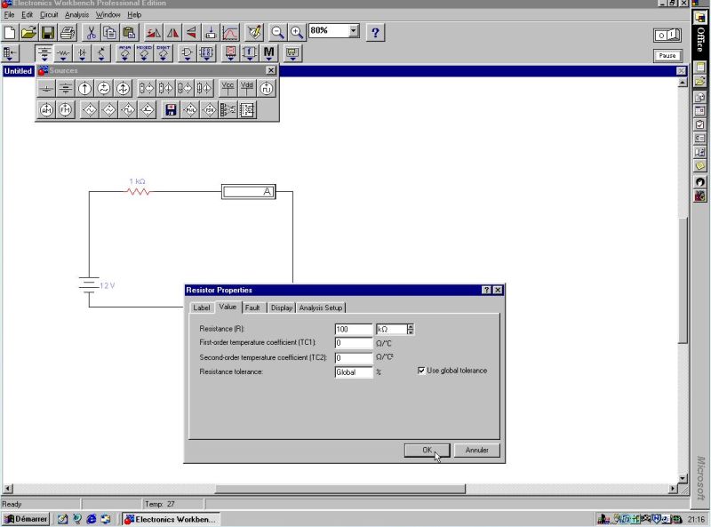
To set the values of a component (resp. to change the default values), simply right-click it and choose Open. This will show the Properties window for this component, and you can set your values. The screenshot below shows a very simple circuit with a power supply, an ampere-meter and a resistor. Using the Properties window of the resistor, I changed the resistance value from 1 kΩ to 100 kΩ.

|
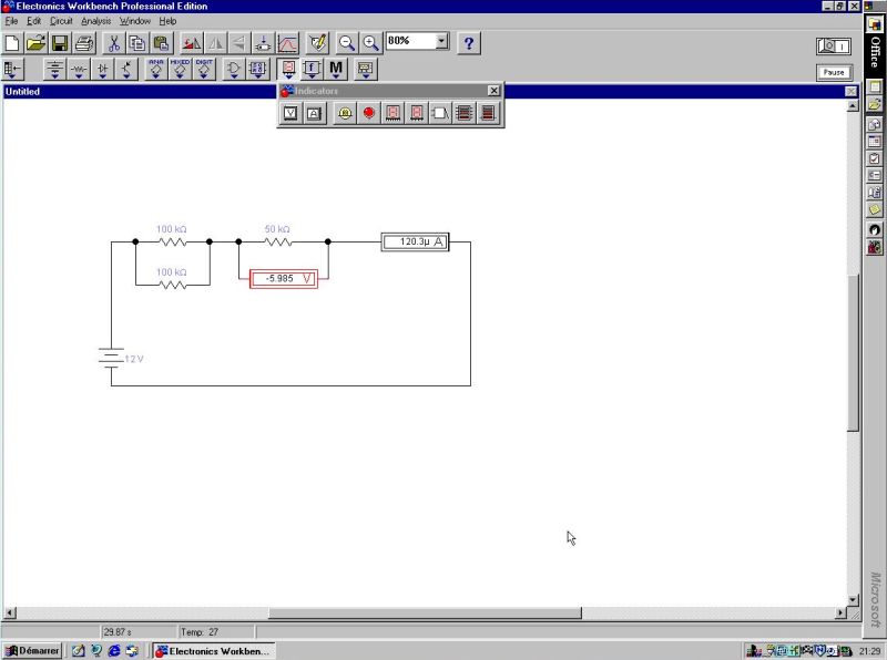
What now, if we want to add another resistor in series with the first one? Do we have to disconnect the wires, insert the new component and redo the wiring? Not at all! First, we can "make place" for the new component by simply dragging the vertical wire at the right of the circuit to the right. The two horizontal wires, that it is connected to, increase automatically in length, the other components are not affected. And to add the new resistor, just drag it onto the upper horizontal wire; it will be automatically connected by its two connection ends. Amazing!
I then added a third resistor in parallel with the first one. And finally I inserted a volt-meter to read the voltage at the connections of my second resistor. Lets apply Ohm's law: R = (R1*R2)/(R1+R2) + R3 = (100*100)/(2*100) + 50 = 50 + 50 = 100 kΩ. I = 12V / 100kΩ = 0.12 mA = 120µA. And the voltage across R3 is 50kΩ * 0.12mA = 6V.

|
The application includes lots of other components: capacitors, diodes, transistors, logic gates and various ICs. It also includes some nice features like copying the circuit as bitmap image and exporting the circuit to Spice. Enjoy!
If you like this page, please, support me and this website by signing my guestbook.